What kind of radio equipment do you use?
There are only a few radio frequency bands that are open for the public to use without a license, and by far the best one for streaming data is the 900mhz spectrum. Radios are (fairly) inexpensive and can be used almost indefinitely. I say fairly because relative to the cost of replacing all your equipment, a few hundred bucks is well worth the price.
Other spectrums are available, but they either can’t span the distance required (smaller XBees) or require too much power to operate during flight (such as 2.4/5.0GHz - e.g. wifi)
Two that I have used are:
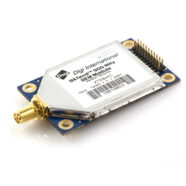
This is my Go-To, as we have seen comm distances of well over the specified 40 miles. It also supports bi-directional mesh networking for multiple chase teams (we usually have several on the ground and one in the air).
These things are pretty much bullet proof. We’ve not seen one failure in the field with these radios. That comes with a price though, by time you get two radios and batteries to power them - you’re looking at well over $500, before you have any GPS or other devices feeding data through.
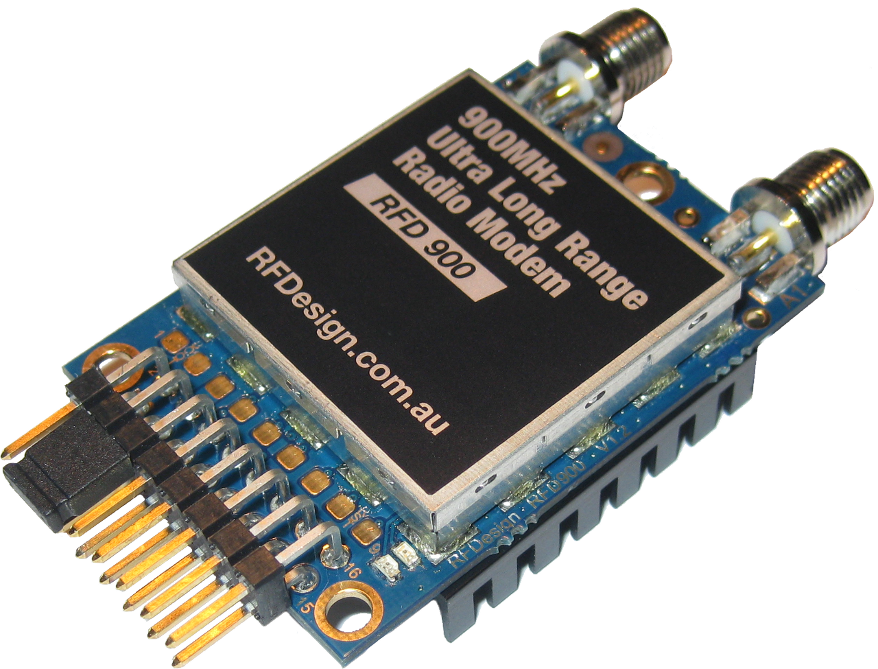
These are slightly more cost effective and have the benefit that all the firmware is entirely open source. You can easily flash the 1.x firmware (Point-To-Point) or the 2.x firmware that supports multipoint. There were some issues with the old version of the modem, but the RFD900+ version appears to have fixed that. I haven’t been able to reproduce the old error on the “plus” model.
One of the best features of this radio is the diversity antennas - which select the best antenna to send/receive on dynamically.
It is also worth noting that while this modem reports that it is FCC Compliant, it is not officially FCC Certified. It’s my understanding that you can technically use these to evaluate them, but you shouldn’t buy through a US distributor - go straight to the manufacturer. The few times I have ordered from there I have gotten the radios within 5 business days (not to bad for the long jump across the pond).
The perk to this, however, is that the radios are more cost effective - you can get two of these radios for just north of the cost of a single XTend (~$200). They can perform comparably in every way, and are becoming my preferred radio.
1 Like
RFD900/RFD900+ Firmware Flashing
Let’s set up our RFD900 radios! Note that we are running firmware 2.5 on our radios in the lab.
I’m assuming that you have the RFD Starter Kit (or equivalent items) which should include:
- 2xRFD900+ Radios (All commands below are for the
+model, if you have the former RFD900, drop thepfrom the name below in commands) - 1xFTDI Cable
- 4xAntenna (2xShort, 2xLong)
If you haven’t yet installed the FTDI Drivers, please do so now.
If you have windows (or run Mono)
You have the option of using the graphical configuration tool [thanks @KReeve_2 for the tip!].
This allows you to both flash new firmware and configure the radio, so you can skip this whole entry and jump down to the RFD900 Configuration entry below.
Get the Firmware
There are two main branches of the firmware:
-
SiK(e.g. 1.x): This supports Point-to-Point communication only -
SiK_Multipoint(e.g. 2.x): This supports both Point-to-Point and Point-to-Multipoint
Download precompiled (only for the RFD900+)
Get it here, choose the 2.5 or 1.12 for the RFD900+. Jump down to [Flash the firmware].
Manual Compilation
Don’t worry about this, it isn’t as hard as it sounds! I’ll try to break out system specific instructions that you can just copy and paste, feel free to dig in where your interests are peaked and leave some replies with specific questions or tips to share!
Note: If the step isn’t broken out by the system name, it should be the same cross platform.
Prereqs:
gitg++makesdcc
Mac:
- XCode Installed (at a minimum the command line tools):
xcode-select --install- homebrew
- sdcc:
brew install sdcc
Linux:
Install the dependencies with:
sudo apt-get install -y git g+ make sdcc(assuming you are on a debian system, e.g. Debian, Ubuntu, Mint, Raspbian)
Windows:
…unknown - I need to test this…
Getting the code and compiling
This is all done in your terminal 
- Get the source code:
git clone https://github.com/RFDesign/SiK.git - Go into the
SiK/Firmwarefolder with:cd SiK/Firmware - Compile the code for your radio with
make install~radio~rfd900p(if you have a different radio, runmake helpand look for your radio name). This should be less than a minute on any hardware (my laptop ~1s, rpi2 ~35s) - Assuming that was successful, you should now have a
dst/folder with the firmware file, specifically you are looking fordst/radio-rfd900p.ihx
Flash the Firmware
This will install the firmware file to your radio, repeat for each radio!
Prereqs
Macintosh / Linux
You have a version of
pythonthat should be suitable installed by default, you’ll need to install pyserial.Option 1 (automated):
If you have a program called
pipinstalled simply runpip install pyserial.Option 2 (manual):
- Download the tarball from here
- Unarchive it with:
tar -xvf ~/path/to/downloaded/pyserial-2.7.tar.gz- Enter the extracted directory:
cd pyserial-2.7- Install with
python setup.py install(note: You may need to prependsudo, but only do it if your environment prompts that you didn’t have permission - don’t ever arbitrarily usesudo!)
Windows
You don’t have a version of python installed by default, download
python2.For pyserial could install from source (see Macintosh / Linux above), but may as well just use the installer from here - make sure to get the one for your python version (2).
If
pythonis not in your%PATH%(e.g. in yourcommand lineyou get an error trying to runpython), simply substitute my use ofpythonwith the path to your installation. e.g.C:\Program Files\python2.7\python.exe
To determine the port all systems can do the following:
- Connect your radio
- Launch a python interpreter in your shell:
python- Import the serial tools:
from serial.tools import list_ports- Run:
list_ports.comports()
On mac/linux the one you want likely resembles:
/dev/tty.usbserial*. Alternatively, you should be able see the serial device withsudo dmesg | grep tty, it should be a recent entry (toward the bottom of the list)On windows it will be
COM#, the number is a literal numeric digit. Alternatively, you can look in yourDevice Manager(use Windows Search to find it)
Note: If you are unsure which port is the right one, unplug your radio modem and re-run the above to see what is persistent.
Flash it
If you’re not still in the SiK/Firmware folder, go back there in your command line.
Assuming that you haven’t changed your baud rate on the radio, you can simply flash your radio with the following, substituting the port path and firmware file for the ones you need (radio~rfd900p.ihx for the RFD900+, radio~rfd900.ihx for the RFD900):
python ./tools/uploader.py --port /dev/tty.usbserial-AL00KJY9 ./dst/radio\~rfd900p.ihx
One windows that would look like (notice the slashes being opposite above):
c:\program files\python2.7\python.exe tools\uploader.py --port COM3 dst\radio\~rfd900.ihx
Congratulations, you should now have the latest and greatest firmware on your RFD900! Check back for the Configuration Guide to come.
RFD900 Configuration
Note that on windows (or if you know how to compile c# programs with mono) there is a configuration tool
Reference:
You need a serial terminal to configure your radio, a free and easy one is coolterm. It’s cross platform, so we can all be looking at a very similar thing, but use your preferred way of connecting to a serial device.
Disclaimer: At the moment, we only have the RFD900+ on hand to test, however, unless you already own a set - these are what you will be getting (which is a good thing!).
Multipoint Firmware Settings
The 2.x firmware is what we currently have installed and our working configuration for either Point-to-Point or Point-to-Multipoint is as follows for testing in the lab:
FORMAT=27
SERIAL_SPEED=9 # This is your baud rate, e.g. the speed your computer (or arduino) talks to the radio at, it's okay if radios don't match.
AIR_SPEED=64 # Lower is generally better for distance, use 16 for flight, Must Match across all nodes.
NETID=25 # These must match on all nodes
TXPOWER=20 # Higher is better for flight, as long as your power supply can handle 5v@~800mA
ECC=0
MAVLINK=0
OPPRESEND=0
MIN_FREQ=902000 # Note that we are based in the US, your country may have different restrictions.
MAX_FREQ=928000 # I think this is legal wherever, but double check!
NUM_CHANNELS=50 # Must match on all nodes
DUTY_CYCLE=100
LBT_RSSI=0 # Must Match on all nodes
MANCHESTER=0 # Must Match on all nodes
RTSCTS=0
NODEID=1 # Duplicates are not OK!  Node 0 should be your balloon
NODEDESTINATION=65535 # If you are using multipoint, this "broadcasts", you can choose to only send to a single node by listing the node id.
SYNCANY=0
NODECOUNT=3 # Total number of nodes, this must be >= your node ID (must match across nodes)
Command Mode
Command mode lets us customize radio settings using the “AT Command Interface”
- Enter
+++and don’t hit anything else for 1s (you will seeOK, note: do not hit the key after the `+++1)- If you are using the Arduino or Code Bender serial monitor, ensure that “No line ending” is selected before you enter the
+++! All other commends want CR+NL(\r\n), however.
- If you are using the Arduino or Code Bender serial monitor, ensure that “No line ending” is selected before you enter the
You can now use any of the AT Commands to configure your settings to your operational requirements.
To set ours up (anything prepended with a [number] is a response from the radio, don’t enter stuff past #, that is to signify a comment to clarify what we are doing here):
+++ # wait 1s, don’t hit
[1] OK
ATI # Check the firmware version
[1] MP SiK 2.5 on RFD900P
ATI5 # List all current radio settings (this is on my freshly flashed radio)
[1] S0: FORMAT=27
[1] S1: SERIAL_SPEED=57
[1] S2: AIR_SPEED=64
[1] S3: NETID=25
[1] S4: TXPOWER=20
[1] S5: ECC=0
[1] S6: MAVLINK=0
[1] S7: OPPRESEND=0
[1] S8: MIN_FREQ=915000
[1] S9: MAX_FREQ=928000
[1] S10: NUM_CHANNELS=50
[1] S11: DUTY_CYCLE=100
[1] S12: LBT_RSSI=0
[1] S13: MANCHESTER=0
[1] S14: RTSCTS=0
[1] S15: NODEID=1
[1] S16: NODEDESTINATION=65535
[1] S17: SYNCANY=0
[1] S18: NODECOUNT=2
ATS8=902000 # Set the min_freq parameter
[1] OK
# Continue setting your parameters…
AT&W # Write the params to memory
[1] OK
ATO # Exit command mode
1 Like
This radio worked really good on our flight to 115k feet.
2 Likes
Do any of you have experience using RFD900+'s in multipoint mode with a high altitude balloon project? My idea is to have two ground stations, one at our launch zone, and the other at our predicted landing zone.
Our ideal situation would have the balloon payload radio transmitting telemetry to both ground units, and have either ground unit able to take control and send control commands to the APM/Pixhawk onboard the payload.
We have not flown this type of configuration at Ardusat yet. Great idea, would love to learn more about your HAB mission.
Yeah! We have at EDGE Research Lab a few times. Basically make the balloon NODE-0 and the other two NODE-1 and NODE-2, use 65535 as the NODEDESTINATION. All radios should be able to talk to each other if all radios are set up that way.
If you only want to multicast from the balloon, you should be able to just set it to NODEDESTINATION 65535 and not really worry about what the nodes are. I bet this would be a fun experiment for new pilots to try out, see if they can all program arduinos or pis to echo messages between nodes 
Hi I am trying to build a HAB using an Arduino Uno paired with these antennas and have a couple of questions. The first question is once you have the radio flashed with the correct firmware and configured how do you use the Arduino with the radio. Is it as simple as wiring the rx and tx of the Arduino and radios together correctly and then using serial commands like write() in the IDE to send data in binary? Also what program do you use on a computer to interpret/display the information coming from the balloon radio?
Thank You
 Sorry for the delay getting back to you! My guess is by now you have tested that out and already have it working - but in case not…!
Yes, to use this with an arduino (or any other device) the device needs to support “Serial” communication. Wiring up TX/RX and you should be able to use the standard Serial.write commands.
Viewing it on a computer really comes up to what you plan to do with the data, at Ardusat we have wired those into the Experiment Platform and charted the data live. In other cases if the data is GPS data it can hook into some mapping applications (Street Atlas from Delorme is what a number of Balloon chasers use).
Please tell me about the best and compatible radio if I want to transmit live data from an ardusat kit inside a HAB